机械臂运动学
准备工作做好了,可以用数学运算来描述位置关系了。
首先推导相邻连杆坐标系变换的形式,然后就可以用复合变换求出机械臂末端相对于基座的位置了。
相邻连杆变换
也即如何从这个坐标系走到下一个坐标系,如何得到两坐标系之间的变换矩阵。
前面有两种坐标系的设置方式,这里也要分开讨论。
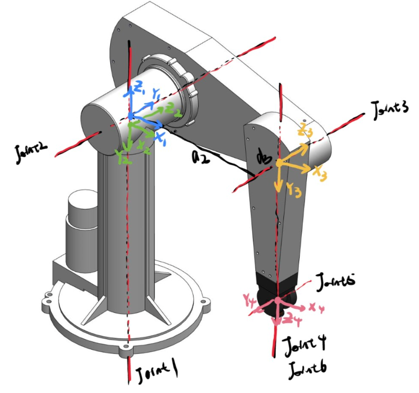
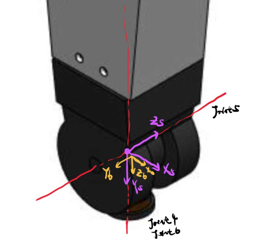
头部坐标系
坐标系固定在头部,《机器人学导论》的方式,使用书里的插图,
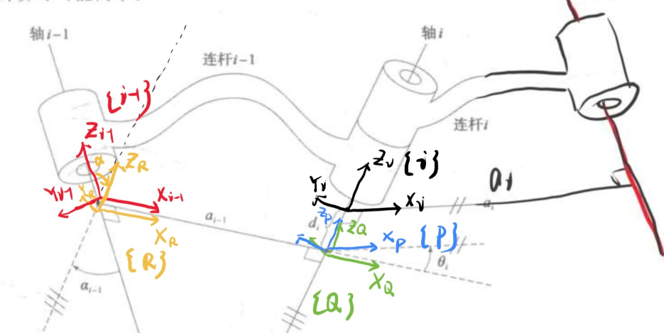
如图所示,即我们希望找出 \(^{i-1}_i T\)
为了解决这个问题,找出3个中间坐标系,每次只完成一个参数的变换,就可以推导出来了。
\[^{i-1}p = \ ^{i-1}_R T \ ^R_Q T \ ^Q_P T \ ^P_i T \ ^{i}p\]复合变换用一个矩阵来表示
\[^{i-1}p = \ ^{i-1}_i T \ ^{i}p\]按照前面的 4 步,这个变换实际上就是
\[\ ^{i-1}_i T = R_X(\alpha_{i-1}) D_X(a_{i-1}) R_Z(\theta_i) D_Z(d_i)\]这个式子的理解方式,从前向后看,相对与当前位姿做操作,从后往前看,相对于世界参考坐标系。
使用前面的旋转矩阵和平移矩阵,乘起来就可以了,也很容易
\[\ ^{i-1}_i T = \left [ \begin{array}{} c\theta_i & -s\theta_i & 0 & a_{i-1} \\ s\theta_i c\alpha_{i-1} & c\theta_i c\alpha_{i-1} & -s\alpha_{i-1} & -s\alpha_{i-1} d_i \\ s\theta_i s\alpha_{i-1} & c\theta_i s\alpha_{i-1} & c\alpha_{i-1} & c\alpha_{i-1} d_i \\ 0 & 0 & 0 & 1 \\ \end{array} \right ]\]这个是最一般的情况,4个参数都不为0。
连续变换就是把每个变换乘起来
\[^0_N T = \ ^0_1 T * \ ^1_2 T * \ ^2_3 T\cdots * \ ^{N-1}_N T\]矩阵 \(^0_N T\) 是关于 n 个关节变量的函数,只知道了每个关节的位置,机械臂末端在笛卡尔坐标系(笛卡尔空间)里的被指和姿态就能计算出来了。这就是正运动学。
尾部坐标系
对于坐标系固定在尾部,也是一样的想法,使用上一节的插图
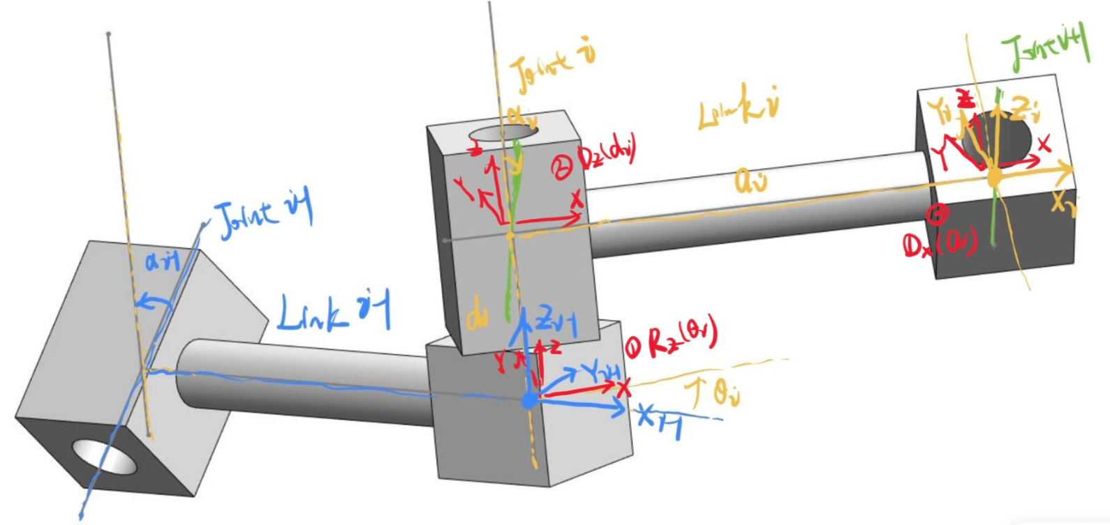
红色为中间坐标系。这个变换顺序
- 绕 \(Z_{i-1}\) 旋转 \(\theta_i\)
- 沿着 \(Z_{i-1}\) 移动 \(d_i\)
- 沿着 \(X\) 移动 \(a_i\)
- 绕 \(X\) 旋转 \(\alpha_i\)
表达式为
\[A_i = Rot(z, \theta_i) Trans(0,0,d_i) Trans(a_{i-1},0,0) Rot(x, \alpha_i)\]这里用了用一种符号,和前面的只是形式上的区别。
同样计算后为
\[A_i = \left [ \begin{array}{} c\theta_i & -s\theta_i c\alpha_{i-1} & s\theta_i s\alpha_{i-1} & a_{i-1} c\theta_i \\ s\theta_i & c\theta_i c\alpha_{i-1} & -c\theta_i s\alpha_{i-1} & a_{i-1} s\theta_i \\ 0 & s\alpha_{i-1} & c\alpha_{i-1} & d_i \\ 0 & 0 & 0 & 1 \\ \end{array} \right ]\]##
上面的式子是最一般的情况,实际机械臂在设计的时候都是有讲究的。不论怎么设计,正运动学设计反正都是一路乘下去。但是要走回来就不容易。
比如关节的扭转角,一般都是0或者90
一般的工业机器人都会做成腕臂分离的形式,这样的设计也是从逆运动学考虑的,即 456 轴做成球形轴,不会有长度。
每个机器人都会有一个表,Kinematics Table,给出机器人的关节参数
| Joint | \(\theta\) | \(d\) | \(a\) | \(\alpha\) | Joint variable |
|---|---|---|---|---|---|
空间
笛卡尔空间,3 维空间,也叫任务空间、操作空间,选定世界坐标系后,3 维向量表示。
关节空间,每个关节有一个转角,组成的 n 维向量。
运动学分析
坐标的定义并不是唯一的,最后达成目的就行,能精确的刻画最后的结果就可以,无所谓中间怎么定义。因此有些轴偏距并不是必须的。